
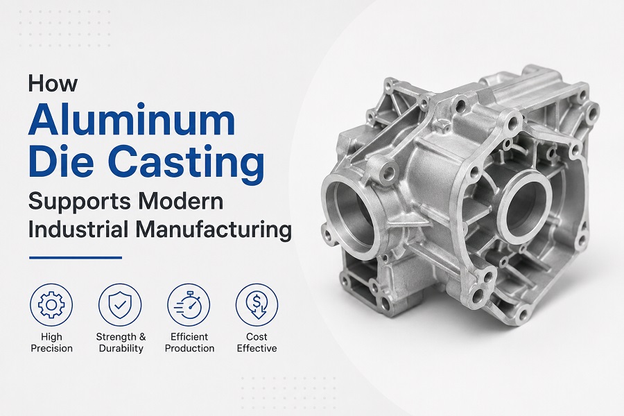
Modern manufacturers need metal parts that combine low weight, useful strength, accurate dimensions, and stable quality. Aluminum die casting meets these needs in many high-volume projects. The process can form detailed shapes quickly and repeat the same shape across a long production run.
A capable die casting service can manage the full route from mold design to casting, machining, surface treatment, and inspection. This connected approach helps engineers match each production step to the part drawing. It can also reduce delays that occur when several suppliers handle separate stages.
The process still requires careful planning. A poor wall design can restrict metal flow. Weak venting can trap gas. An unsuitable finish can raise cost without improving performance. A strong project starts with clear part requirements, realistic production volumes, and early discussion between the product designer and the casting team.
What Is Aluminum Die Casting?
Aluminum die casting is a manufacturing process that injects molten aluminum alloy into a reusable steel die. High pressure forces the liquid metal into the die cavity. The metal then cools and becomes solid. The machine opens the die, ejects the casting, and begins the next cycle. The North American Die Casting Association describes the same basic sequence and notes that rapid cooling forms the final shape.
Most aluminum parts are machined on a cold-chamber machine. A furnace melts the alloy outside the injection unit. A ladle or automated system transfers a measured amount of metal into the shot chamber. A plunger then pushes the metal into the closed die. Manufacturers use this method because molten aluminum can react with parts of a hot-chamber injection system.
The process suits medium and high production volumes. Steel tooling requires a significant initial investment. Each later cycle can produce a part in a short period, so the unit cost often falls as production volume rises. This cost pattern makes die casting a strong option for repeat orders, but it may be a poor choice for a very small batch.
Aluminum alloys offer several useful properties. They have a good strength-to-weight ratio, useful corrosion resistance, and good thermal conductivity. They also keep stable dimensions under many operating conditions. These properties support housings, brackets, heat sinks, covers, tool bodies, and structural parts. Common die-casting alloys include A360, A380, and A383, with regional equivalents such as ADC-3 and ADC-12.
Die casting can also form thin walls, ribs, bosses, mounting points, and other details in one part. This feature can replace an assembly that once used several pieces and fasteners. Part consolidation can cut assembly time and reduce the number of items in a bill of materials. Engineers must still check load paths, wall thickness, draft, and local stresses before combining several functions in a single casting.
The process has limits. High-speed metal flow can trap air and create porosity inside a casting. Thick and thin sections can cool at different rates. Sharp corners can increase stress and block smooth metal flow. Engineers control these risks through part design, gate and runner design, venting, die temperature, injection settings, and inspection. High-vacuum and squeeze-casting methods can reduce gas content for parts that need higher integrity.
From Mold Design to Finished Components
A die-cast part begins as a product idea, but the mold controls how that idea becomes metal. Engineers first review the 3D model, the drawing, the alloy, the annual volume, and the required tolerances. They also identify critical surfaces, sealing areas, threads, cosmetic zones, and points that will receive a later coating.
The design team then checks whether molten metal can fill the part without early freezing or trapped gas. Uniform walls usually support stable flow and cooling. Draft angles help the solid part leave the die. Rounded internal corners reduce stress and improve filling. The team must also choose a parting line, which marks the place where the two main die halves meet.
The mold contains more than the visible cavity. Runners carry the molten alloy. Gates control the entry of metal into the cavity. Vents let air leave as metal enters. Cooling channels remove heat from the tool. Ejector pins push the solid casting out after cooling. Slides or movable cores can create side openings and other features that a simple two-part die cannot form.
Engineers often use mold-flow simulation before tool construction. The software can show fill patterns, cold zones, air traps, and areas with uneven solidification. A team can then adjust the gate, vent, wall, or overflow design before it cuts expensive tool steel. Simulation does not remove the need for trial runs, but it gives the team a clearer starting point.
Toolmakers build the die after the design review. They machine hardened tool steel, assemble the moving sections, and connect the cooling system. The casting team then runs initial samples. Inspectors compare the samples with the approved drawing. Engineers may change process settings or modify the die before the customer approves mass production.
Production follows a repeated cycle. The machine prepares and closes the die. The system injects the alloy. The part cools under controlled conditions. The die opens, and ejector pins release the casting. A press or trimming tool removes runners, gates, and flash. Operators may also deburr edges or use shot blasting to create a clean and even surface.
A real production example shows how these decisions connect. JoinCast lists an aluminum outboard lower-unit housing made from ADC-3 or A360 alloy with chromate conversion as the finish. The company also lists pneumatic tool housings made from ADC-12 or A383 with paint or powder coating. Each part uses a different mix of alloy properties, geometry, machining needs, and surface protection.
A complete production plan should define every stage before the supplier quotes the job. The drawing should identify dimensions that need machining, surfaces that need coating, and areas that must remain free from coating. It should also state testing rules, sample approval steps, packaging needs, and order volumes. Clear inputs reduce later changes and help the supplier set a realistic cost.
The Role of CNC Machining and Surface Treatment
Die casting can form many features close to their final size, but it cannot finish every detail. CNC machining creates critical holes, threads, sealing faces, bearing seats, and mating surfaces. It also brings selected areas to tolerances that the casting process alone may not hold.
The production team should machine only the features that need it. Extra machining adds cycle time, fixtures, tools, inspection work, and scrap risk. Early design review can keep important dimensions in easy-to-reach positions. It can also prevent a tool from cutting through a thin wall or exposing internal porosity.
Good fixture design supports repeatable machining. The fixture must locate the casting from stable reference points. It must hold the part without bending a thin wall. The machining program must also account for small casting variations. A poor fixture can create dimensional errors even when the CNC machine itself works correctly.
Surface treatment serves several possible goals. A coating can improve corrosion resistance, colour, wear resistance, electrical behaviour, or appearance. The correct choice depends on the alloy, the operating environment, the contact surfaces, and the customer specification. Dynacast notes that a casting does not always need a finish and recommends selecting one according to function and process control.
Powder coating gives parts a durable coloured surface and works well for tool bodies, equipment housings, and outdoor products. Chromate conversion can protect aluminum while keeping an electrically conductive surface. Anodising can add corrosion and wear resistance, although alloy chemistry and casting quality affect the final appearance. Paint can meet colour and branding needs. Impregnation can seal connected porosity in parts that must hold air or liquid.
Surface preparation affects the result. Oil, release agent, oxide, burrs, and loose particles can reduce coating adhesion. Suppliers may use cleaning, polishing, shot blasting, or chemical preparation before coating. They must protect threads, sealing faces, and electrical contact points when those areas cannot accept a coating.
Marine parts provide a clear example. Salt water can attack an unprotected surface and can enter small defects. The manufacturer may select a corrosion-resistant alloy, apply chromate conversion or paint, and confirm performance through salt-spray testing. The coating cannot correct a weak casting, so the team must control both the base part and the finish.
Heat sinks require a different plan. Aluminum transfers heat well, but the part still needs a sound thermal path, suitable fin geometry, and clean contact surfaces. A coating may change heat transfer or electrical isolation. Engineers must evaluate the complete thermal system instead of choosing a finish for appearance alone.
Quality Control in Aluminum Part Manufacturing
Quality control starts before the first production cycle. The drawing must define the features that affect fit, function, safety, and appearance. The control plan must then match each feature with a measurement method, sample rate, and acceptance limit. This method focuses inspection work on real product risks.
Material checks confirm that the alloy matches the specification. A spectrometer can measure the chemical composition of a sample. Process records can track melt temperature, die temperature, injection settings, cooling time, and other production values. Stable records help a team detect a shift before it creates a large batch of defective parts.
Dimensional inspection compares the casting and machined features with the drawing. Calipers and gauges can check simple dimensions. A coordinate measuring machine can check a detailed set of points and geometric tolerances. A 3D scanner can compare a broad surface with the digital model. Surface-roughness equipment can check machined or finished areas that need a defined texture.
Visual inspection can find flash, cracks, incomplete filling, dents, stains, and coating faults. Leak testing can check housings that carry air, oil, or water. Salt-spray testing can support corrosion checks for marine and outdoor parts. X-ray inspection can reveal some internal voids without cutting the part, while destructive sectioning can support process studies and validation.
A real supplier example shows how these tools can work together. JoinCast states that its inspection resources include Mitutoyo coordinate measuring machines, Keyence 3D scanning, material spectrometry, salt-spray testing, and surface-roughness checks. The correct test set still depends on the part. A painted tool housing does not need the same control plan as a pressure-tight marine housing.
First article inspection gives the customer a detailed check before full production. The report can list drawing dimensions, measured results, material data, finish records, and part photographs. Customers can use the report to approve the process or request corrections. Later production inspections confirm that the approved process remains stable.
Traceability connects each shipment with its material batch, production date, machine, tool, process records, and inspection results. This information helps the supplier contain a problem if a customer reports a defect. The team can identify affected lots instead of treating every past shipment as suspect.
Quality also includes communication. Engineers need a clear method for design changes, deviation requests, nonconforming parts, and corrective action. A fast reply has little value if it lacks measurements and root-cause evidence. A useful corrective action explains what failed, why it failed, what the supplier changed, and how the team confirmed the result.
Industries That Use Aluminum Die-Cast Components
The automotive sector uses aluminum die-cast housings, brackets, covers, structural parts, and thermal components. Manufacturers value low weight, repeatable dimensions, and high production speed. The exact process depends on the load, crash requirements, heat exposure, joining method, and expected production volume.
Marine equipment uses housings, mounts, engine parts, and deck hardware. These parts face moisture, salt, vibration, and impact. Designers often combine suitable alloys with machining, sealing, coating, and corrosion tests. An outboard housing is a useful example because it needs accurate interfaces and reliable surface protection.
Pneumatic tool makers use die-cast bodies and housings because the process can create a light shell with ribs, air passages, mounting points, and a grip shape. CNC machining can finish valve bores, threaded ports, and sealing faces. Powder coating or paint can protect the exterior and provide brand colour.
LED lighting and power electronics use aluminum housings and heat sinks. Die casting can form fins, mounting features, cable entries, and protective walls in one component. Designers must allow the metal to fill narrow features and must keep the thermal path effective. Machining can create flat contact areas for circuit boards or thermal pads.
Medical equipment manufacturers can use die-cast parts in lighting arms, equipment mounts, pump housings, and diagnostic machine structures. These parts may need accurate dimensions, cleanable finishes, and complete inspection records. The product team must check all regulatory and performance requirements because a general industrial process certificate does not replace product approval.
Agricultural and general industrial machines also use aluminum castings for covers, controllers, handles, and equipment housings. These parts may face dust, rain, chemicals, vibration, or frequent handling. The team can match alloy, wall design, coating, sealing, and tests to the actual work setting.
Aluminum die casting gives manufacturers a practical route from a detailed digital model to repeatable metal components. Its strongest use case combines stable design, medium or high volume, and a clear need for integrated shapes. The process can reduce assembly work and support consistent production, but it demands sound tooling, controlled metal flow, suitable machining, and focused inspection.
A buyer should compare suppliers by technical fit instead of price alone. The review should cover mold engineering, machine range, alloy experience, machining capacity, finish options, measurement equipment, documentation, capacity, and communication. These factors show whether a supplier can control the full production route and deliver a part that performs as the drawing requires.
